VQC
扫描+远心光学
台面中部623.39 mm
台面左侧623.44 mm
两处均在公差内
两次读数相差 0.05 mm


Scan flat parts and check profiles, holes and positions against CAD.
We measured the same parts at different positions with VQC and with a static imaging system. VQC's readings stayed put. The static system's drifted out of tolerance.
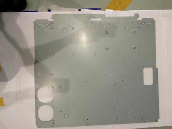
图纸间距:623.40 ± 0.30 mm
允许范围:623.10—623.70 mm。
扫描+远心光学
两处均在公差内
两次读数相差 0.05 mm
本次受测设备:整件一次成像
一处读数超出公差
两次读数相差 0.648 mm
样件检测案例,仅对应所示样件、尺寸、摆位与本次受测设备;不代表整件合格,也不代表所有设备或所有成像方式的表现。读数差不等于准确度或通用重复性指标。
Raised features on both sides · Uneven sheet
| Part position | VQC mm | Static imaging mm |
|---|---|---|
| Centre | 623.39Within tolerance | 623.634Within tolerance |
| Left | 623.44Within tolerance | 624.282Out of tolerance |
VQC: both positions within tolerance. Static imaging: one reading outside tolerance.
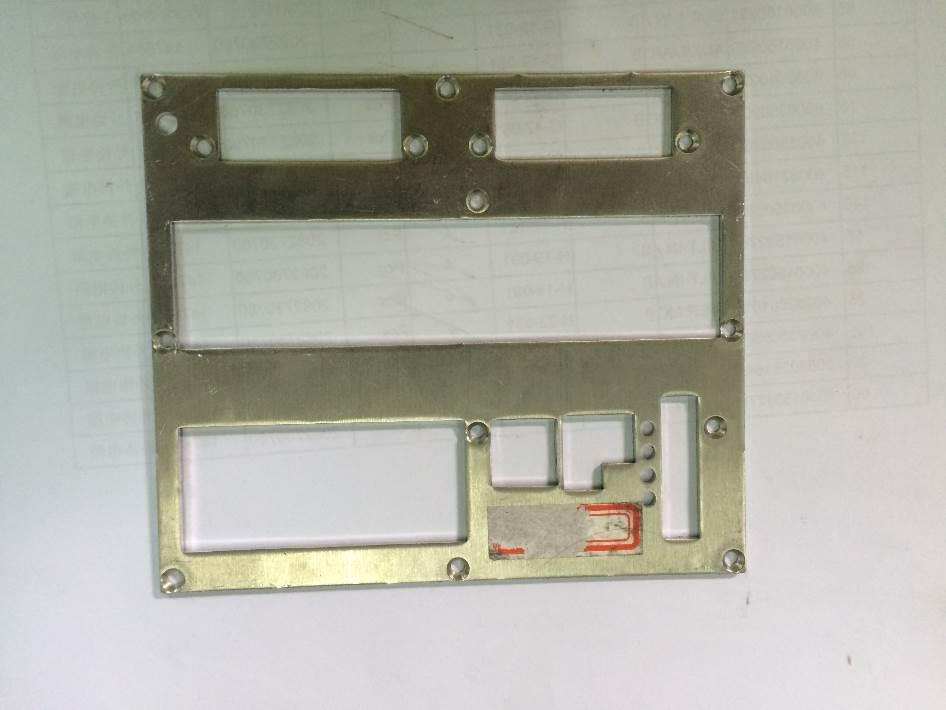
| Part position | VQC mm | Static imaging mm |
|---|---|---|
| Left | 2.88Within tolerance | 3.048Out of tolerance |
| Right | 2.88Within tolerance | 3.165Out of tolerance |
| Centre | 2.88Within tolerance | 2.930Within tolerance |
VQC: 2.88 mm at all three positions. Static imaging: two readings outside tolerance.
Historical comparison from 2016 material: one telecom and one medical sheet metal sample, the dimensions and positions shown. Results apply to these samples only. Your part can be assessed in a sample inspection.

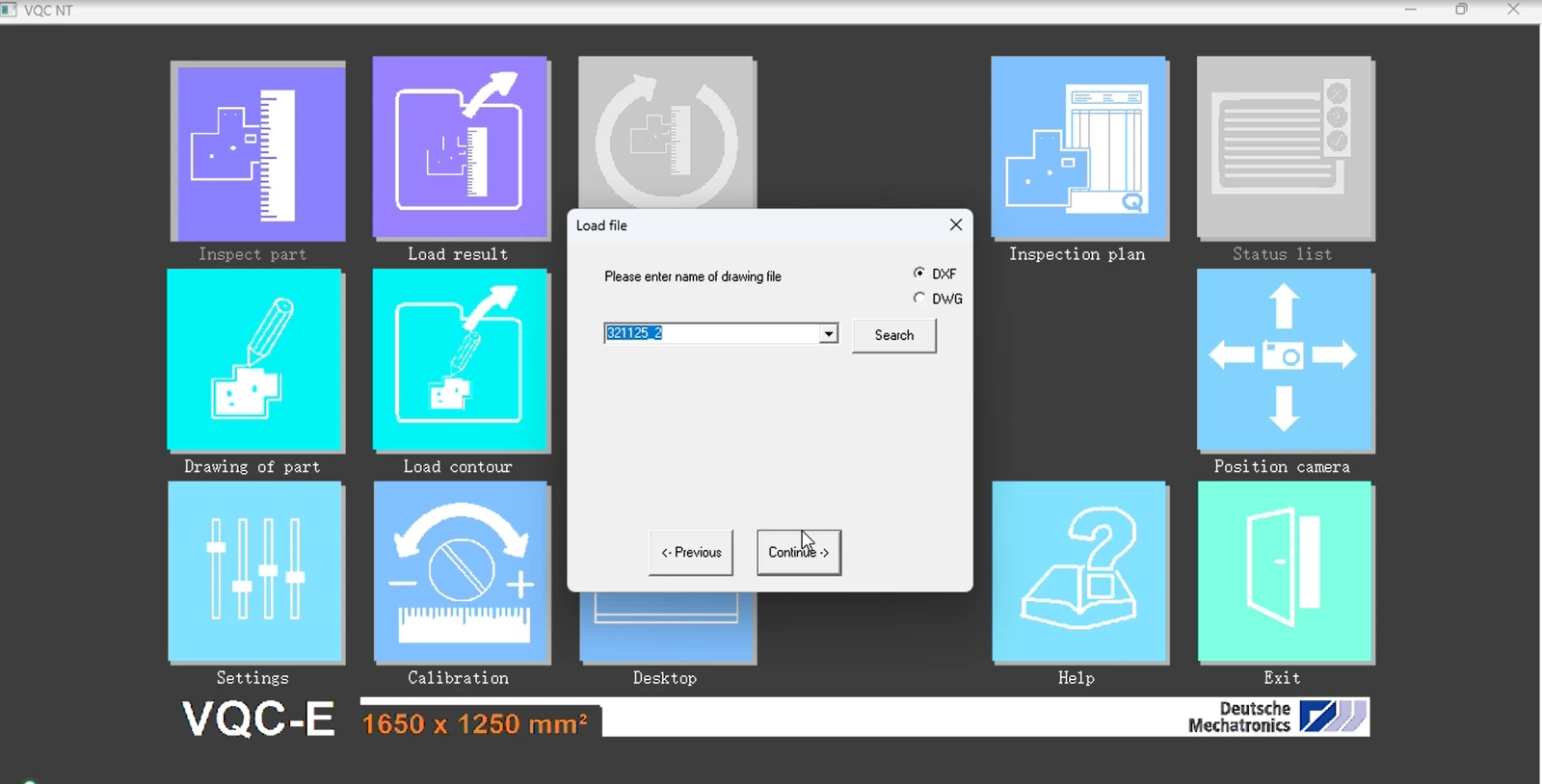
Select the matching CAD / DXF drawing or inspection plan. Nominal geometry and tolerances become the reference for the inspection.
Profiles, holes and dimensions, shown in real inspection results.
Compare the measured outline with CAD to locate deviations, extra cuts or missing cuts.
Read the result: compare the nominal value with the measured value, then check the deviation against the tolerance for that dimension.
Measure circular hole diameters against nominal dimensions and tolerances to check for oversize or undersize holes.
Read the result: compare the nominal value with the measured value, then check the deviation against the tolerance for that dimension.
Check centre-to-centre and hole-to-edge distances to identify positional deviations that may affect assembly.
Read the result: compare the nominal value with the measured value, then check the deviation against the tolerance for that dimension.
The image shows nominal angle and radius annotations from the drawing, not measured results. Confirm the required checks with your drawing and a sample.
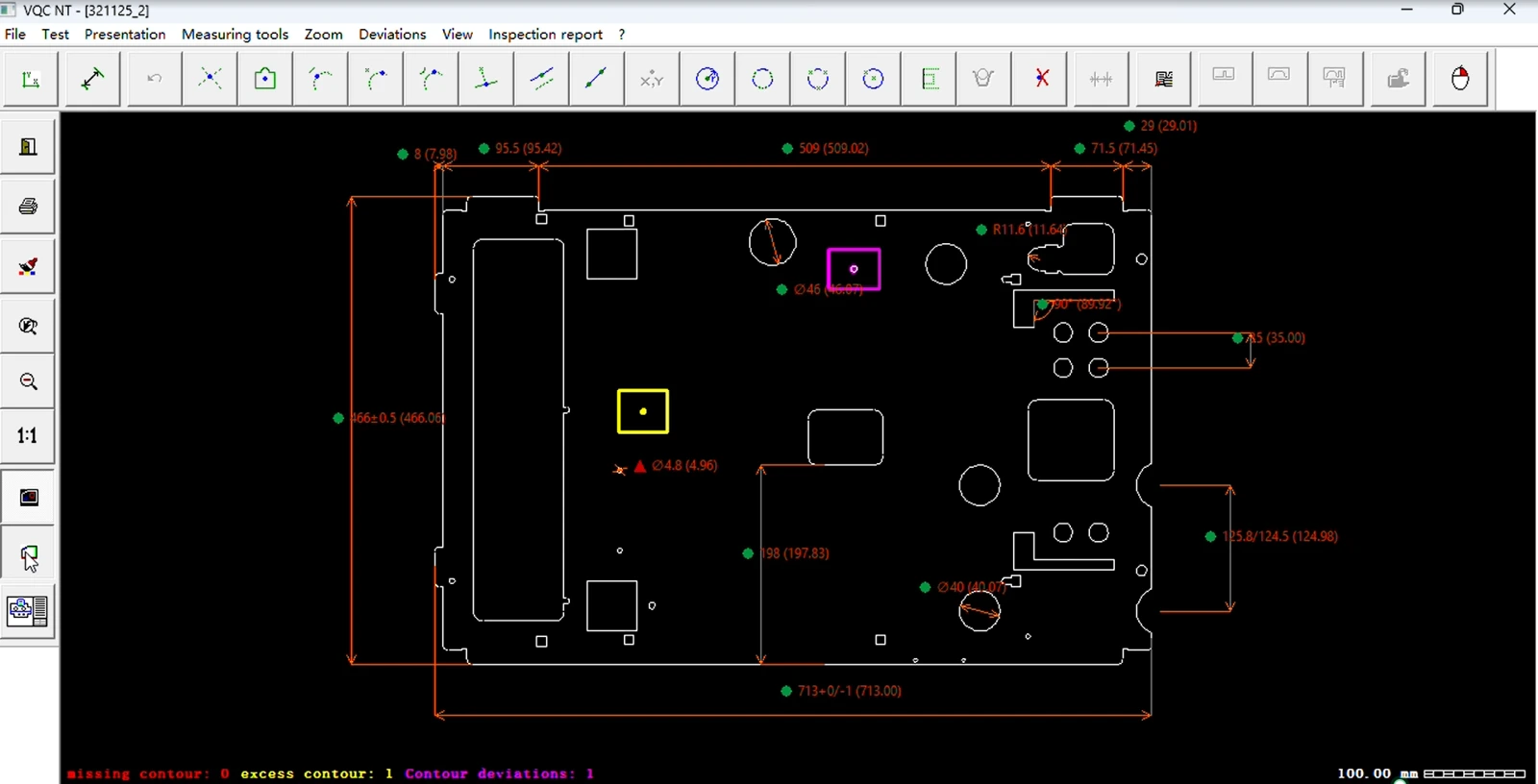
Compare measured profiles and dimensions with CAD to find the areas that need review.
See the spacing results for a sample with raised features on both sides, tested at two positions.
Review nominal values, tolerances, measured values and deviations, then create an inspection report.
Raised or warped parts: suitability depends on height, visible contours and required tolerances. Confirm with a sample inspection.
See the sample results →Nominal accuracy (MPEE)±40 µm
MPEE ±(30 + L/50) µm, with L in mm. Confirm the specification for your configuration.
An ordinary lens looks at the plate edge at an angle: the thicker the plate and the farther from the lens axis, the more the edge appears to move. A telecentric lens looks straight down along parallel rays.
Illustration, not measured data: ordinary lens assumed 2 m above the table; ideal telecentric optics.
Inspect profiles, hole positions and 2D dimensions on opaque flat parts.
Discuss your part ↗ Illustrative example
说明基准、关键尺寸、公差与当前检测难点。
确认可测项目、工件条件与需要适配的功能。
核对样件结果,确定配置与验收要求。
定制范围、费用与周期按项目确认。
VQC checks profiles, hole positions and related dimensions on opaque flat parts. The workflow shown here does not inspect 3D surfaces, thickness or surface defects.
Compare the full loading, scanning, review and reporting cycle using representative parts, alongside your inspection volume and current process.
Bring a representative part, CAD / DXF drawing and key tolerances. Tell us which checks take the most effort.
VQC 是面向平面钣金零件的光学尺寸检测系统。扫描实物轮廓,与 CAD/DXF 比对,检查外形、孔径、孔位和相关尺寸,并输出报告。复杂轮廓可整体查看,重复订单可复用检测方案,超幅零件可采用拼接与多段扫描;特殊检验要求可在机器能力范围内定制。
优先适合激光切割、冲压落料等平面零件制造企业,尤其是多品种、小批量、孔槽多、轮廓复杂或首件检查频繁的生产。若经常需要逐项量尺寸、核对图纸和整理报告,可从这些工作量最大的零件开始比较检测流程。
VQC 主要补充整件平面轮廓与 CAD 的比对,以及孔径、孔距等二维尺寸检查。卡尺适合少量简单尺寸,三坐标可继续承担需要空间测量的项目。选型时用同一零件比较覆盖项目、操作时间和报告内容,确定各设备的分工。
可以。这是 VQC 的主要应用:扫描不透明平面零件的外形、孔和槽,与 CAD/DXF 比较轮廓及尺寸偏差。毛刺、翘曲或遮挡可能影响边缘识别,具体检测项目和公差按图纸与样件确认。
VQC 的二维轮廓检测不限于金属。零件需不透明、边缘可见,并能形成稳定轮廓。透明、半透明或容易变形的材料需先试样,确认透光和支撑是否影响边缘识别。
VQC 12/16 与 VQC 12/20 分别配套不同的相机与远心镜头组合,可按零件幅面和检测任务选择: VQC 12/16:单次测量幅面 1250 × 1650 mm。 VQC 12/20:单次测量幅面 1250 × 2000 mm。
两款均可结合拼接与多段扫描,覆盖超出单次幅面的长件任务。选型时同时考虑常见件、最大件、关键公差与工件支撑,具体配置及可覆盖尺寸按方案确认。
既有型号资料给出的工件总高度上限为 40 mm。这里是二维轮廓检测的工件高度条件,不是激光测高量程,也不表示 40 mm 内的所有折弯面都能测。板厚、支撑后的高度和待测边缘是否可见需一起核对;具体上限以所选配置规格为准。
部分成形件可以按二维轮廓检测,前提是待测边缘可见,并满足高度与支撑条件。已有双面成形样件在不同摆位下的间距检测案例。二维结果不直接包含折弯角、空间形状或鼓包高度;这些项目需另选测量方式。
支持。VQC 可将同一零件分段扫描,再自动关联为整件二维轮廓,用于 CAD 比对、尺寸检查或逆向输出,让超出单次扫描幅面的长件、大幅件也能围绕整件组织检验。
平移续扫支持多段;旋转或翻面流程按两段组织。相邻段通过共同轮廓、孔或 A/B 标记定位,具体段数与可覆盖尺寸按机型、支撑和重叠特征确认。
可检查二维外形轮廓、孔径、孔心距、孔到边缘距离,以及可按方案定义的角度、圆弧半径等项目。将客户关心的尺寸、基准和公差放入同一方案,扫描后统一查看偏差与报告,便于首件确认和交付复核。需要指定位置的相对高差时,可另行评估局部测高配置。
可以。导入对应 CAD/DXF 后,将实测轮廓与图纸对齐,直接查看局部偏差、多加工或漏加工的位置,并按方案检查关键尺寸。复杂边缘可以先看整件差异,再放大复核;图纸版本、单位、基准和公差需在方案中确认。
不能仅凭放上零件就自动理解全部检验要求。新零件需先定义检测项目、基准和公差,保存并验证方案;重复检测时可直接调用。通用公差可以预设并保存,客户指定公差也需有明确来源;图纸变更后应复核方案。
VQC 用相机扫描、远心光学与位置测量系统获取二维轮廓,再与 CAD 对齐。远心光学有助于减小板厚与离轴位置造成的视差;逐幅采集的轮廓关联到测量坐标,支持整件尺寸检查与大件拼接。适用精度以对应配置规格和验收条件为准。
VQC 二维长度测量的产品资料指标为 MPEE = ±(30 + L/50) µm,L 为被测长度,单位 mm。MPEE 指最大允许误差。
按公式计算: 500 mm:±40 µm(±0.040 mm) 1000 mm:±50 µm(±0.050 mm) 2000 mm:±70 µm(±0.070 mm)
能否满足工件公差,还需结合基准、工件状态及验收规则判断。例如,1000 mm 时的 ±0.050 mm 测量指标,不能直接理解为能够可靠判定 ±0.050 mm 的工件公差。指标以具体配置规格和验收条件为准,不适用于激光测高。
不是。重复性说明多次读数是否接近,准确度还要看读数与可信参考值的偏差。验样时应既做独立重复取放,也与同件、同面、同基准的参考测量比较;只看一次合格或多次读数接近,都不足以判断测得准。
不能作所有项目零漏检、零误判的保证。VQC 可做全轮廓 CAD 比对,并按方案核对指定尺寸与公差;检测覆盖哪些项目,需要在方案中明确。缺失、无效或未确认的结果应单独复核,不能按合格处理。
VQC 12/20 成像配置的二维全幅扫描示例: 扫描幅面:2000 × 1250 mm(2.5 m²)。 扫描用时:约 6 分 05 秒至 6 分 17 秒。 按幅面折算:约 0.40—0.41 m²/分钟。
以上为该配置下矩形幅面的纯扫描时间,上料、对齐、评定与报告另计。VQC 12/16 采用另一套相机与镜头组合,其面积用时需按相同口径单独核对。
重复零件可直接调用已确认的图纸、基准、公差和检测方案,再放件扫描,减少重新定义检验要求的工作。新件先建方案并验证,后续相同订单即可复用;图纸、基准或公差变更时更新对应方案。首次准备与日常调用应分开计时。
许多平面轮廓检测任务无需专用定位夹具。VQC 可将实测轮廓与 CAD 对齐,识别零件的位置与方向,减少对精确摆正的依赖。工件仍需合适支撑、保持待测边缘可见并位于有效区域内;易变形件、特殊形状和拼接任务按实际摆放确认。
已有“先二维检测、后局部激光测高”的实机演示。这里的 2.5D 指二维轮廓与尺寸,加上方案指定位置相对参考面的高度差。它不等于连续三维表面扫描;测高选件、可测表面和性能按项目确认,并非全系列标配。
局部测高用于比较指定位置与参考位置的相对高差。已有校验板板面高差和孔内台面粗检演示;沉孔深度、实体凸台、加强筋或翻边高度属于需用实际零件验证的应用。离散测点可反映局部起伏,不能直接代替整面平面度或连续三维面形。
目前没有已确认可作为通用保证值的整机激光测高精度指标,二维 MPEE 公式也不适用于测高。反光、镀锌表面、倾斜和遮挡都可能影响返回信号。应以真实零件在同一测点与可信参考值比对;演示中的读数极差不能当作高度准确度。
可按方案生成包含名义值、公差、实测值、偏差与判定的检测报告,并支持打印、导出和报告项目筛选。让生产复核与客户交付围绕同一组结果沟通,减少重复抄录和整理。
资料列出的导出格式有 ASCII 表格、CSV、Excel 和 GEOPACK;具体交付版本的格式、字段及模板,以原生导出样例确认。
报告与数据导出可作为质量记录的基础。MES 接口、电子签名和不可篡改存档需按项目另行确认。可提供目标系统的零件编号、批次、结果字段和导入样例,按设备能力评估适配范围。
可以。VQC 可把实物的可见二维轮廓扫描为 CAD/DXF,供补图、样件数字化和 CAD/CAM 加工准备使用。超出单次幅面的大件,也可采用拼接与多段扫描获取整件轮廓。输出反映实物形状,设计公差、遮挡结构及加工用途仍需在目标软件中复核。
可围绕冲压、切割等工序安排车间检测位置。布置前应核对整机占地、工件进出方向、上料与维修空间、地面承载、供电和安全区域,并确认温度、振动等是否满足测量要求。具体尺寸、电气与环境条件以所选机型的安装条件表为准。
日常操作培训包括放件与支撑、调用方案、启动检测、查看偏差和输出报告;建方案人员还需学习基准、公差与异常复核。建议直接使用您的实际零件培训,并分别确认“能执行检测”和“能建立方案”的掌握标准;培训天数按交付计划约定。
日常重点是保持测量台面清洁,并按机型要求维护导轨和光源。安装、移机或更换测量部件后需要重新校验;校验周期按使用强度与质量制度约定。软件升级前应核对设备、方案和报告兼容性,升级后复核关键零件结果;异常不能只靠重新校准处理。
价格、交期与保修按机型、选件、定制范围和服务条款报价,目前没有统一可公开的价格或固定回本周期。收益可按同一任务比较:检测人工、首件等待、报告整理与返工成本,再扣除设备、培训和维护投入,避免把重叠时间重复计为节省。
准备代表性零件、CAD/DXF、关键尺寸与公差、材质和高度信息,以及需要的报告样例。试样时约定参考测量方法,分别记录重复取放、参考偏差和完整流程用时;二维与测高分开列出验收项目。试样安排、费用和正式验收条件按项目确认。
可以。VQC 支持在机器能力范围内,按客户图纸定制基准、关键检测项目、公差和报告需求,让检验方案贴合您的生产与交付要求。先确认现成功能与需要适配的部分,再约定费用、周期和样件验收要求;范围以光学、机构、传感器及软件能力为限。
可以按客户定义评估并定制。需要明确基准如何定位、测哪个特征、沿哪个方向计算,以及采用何种公差口径。例如孔位偏差需区分半径口径 r 与直径口径 2r;定义确认后,再在机器能力范围内落实到方案和报告。
可以。VQC 已有报告项目筛选能力,可围绕客户关心的关键尺寸组织结果。指定字段、排序或版式需与当前报告输出核对,超出现成功能的部分可在能力范围内评估定制,并确认样例与验收要求。
多孔、异形边缘和复杂平面轮廓,是 VQC 值得重点评估的应用。实测轮廓与 CAD 整体叠加,可先定位局部异常,再按方案查看孔槽、孔距及关键尺寸,减少围着整件反复找尺寸和抄录结果的工作。基准、项目和公差在方案中预先确认。
首件加工后,调用对应 CAD 与已确认方案,扫描查看整件外形偏差、关键孔位和尺寸,让生产调整有具体依据,再按企业检验规则决定是否放行。保留的结果也方便生产与质量人员共同复核,避免仅凭口头描述沟通偏差。
VQC 可将实测轮廓偏差与关键项目的名义值、公差、实测值和判定整理为结果,便于向客户说明具体哪个尺寸需要复核。按约定图纸版本、基准和字段交付,质量沟通更容易对齐;特殊报告模板可按输出能力评估定制。
重复出现、轮廓复杂或逐项检验费时的零件,优先建立检测方案通常更有价值。一次确认基准、项目与公差,后续相同任务直接复用,逐步形成常用零件的检验方案库。一次性简单任务则比较首次准备与现有量具的工作量,再决定采用方式。
部分经验证适合的二维轮廓、孔径和孔距检查,可安排在车间用 VQC 完成;需要空间坐标或其他三维几何量的项目,继续由相应设备承担。是否转移应按项目清单和公差验证,再比较排队、操作及报告时间。
值得评估。VQC 采集轮廓时无需测头接触待测边缘,可减少接触力引起变形的影响。薄板仍会受重力、支撑和自身翘曲影响,应按实际摆放状态验证;非接触不等于零变形。
将基准、检测项目与公差保存在已确认方案里,操作人员按同一要求调用、放件、检测和复核,减少每次重新解释图纸与设置检验项目的工作。常用零件逐步积累方案,便于培训和重复订单执行;方案变更与异常判断仍需明确负责人。
可把孔心距、孔到边缘距离与定位基准放进检测方案,扫描后由实测轮廓计算并对照公差。超出单次范围的大板可结合拼接,形成整件轮廓后检查跨区域尺寸,让大件检验也能围绕同一张图纸组织。覆盖范围、孔阵关联和跨段关键尺寸通过样件确认。
用同一零件、同一尺寸、公差与摆位要求比较:是否可测、相对参考值的偏差、重复取放表现、完整操作时间,以及报告能否直接使用。还应核对测量范围、支撑、定制和服务费用。VQC 的扫描与远心光学可作为原理差异,采购判断仍以对应任务的结果为准。
可以。已确认的图纸、基准、检测项目和公差可保存在方案中,重复订单调用同一方案,既减少重复设置,也便于团队保持一致的检验要求。零件或图纸变更后,复核更新对应方案,再用于后续批次。
不是所有项目都能测,也不默认免费。定制以机器能力为边界,先区分现成功能与新增适配,再确认工作量、费用、交付周期和验收样例。超出可见轮廓、机构范围或传感器能力的需求,需要另选配置或测量方法。
若复杂件逐项检查费时、重复订单常需重建检验要求,或首件等待和报告整理影响交付,可优先用代表件评估。若零件简单、任务很少且现有量具已满足要求,应先比较总投入与实际节省,再决定配置。
可以。先选高频、难检或影响交付的几种零件,确认可测项目、公差、方案和报告,再逐步增加任务。这样可先建立常用方案与操作经验;新增零件仍需确认适用性,特殊项目可在机器能力范围内定制。
先核对变更的是轮廓、尺寸、基准还是公差,再修改并重新验证对应方案。重复使用时应调用与图纸版本相匹配的方案;若新增项目超出现成功能,可在机器能力范围内评估定制。
VQC 通过相机扫描与远心光学采集轮廓,并关联到位置坐标,服务于整件 CAD 比对、尺寸检查和大件拼接。评估效率时,可同时比较扫描面积、对应配置下的用时,以及上料、评定与报告工作量,更容易看清设备对实际检验流程的价值。
支持多段平移扫描,段数按完整覆盖需要组织,让超出单次幅面的长件也能按整件检查。软件按流程提示续扫,并把已确认的各段关联起来,减少手工整理分段结果的工作。
旋转或翻面流程为两段。可处理的总尺寸受机型、工件支撑、搬件空间和可靠重叠特征限制。
可以在拼接形成的整件二维轮廓上,与同一 CAD 和检测方案进行比对,组织跨段孔距、整件外形及关键尺寸检查,并输出方案结果。客户可围绕整件查看偏差与报告,减少分段结果各自解释的工作。跨段项目、基准和拼接后的测量表现,需随方案验证。
可以。VQC 的拼接流程也用于逆向扫描:把同一大件的各段轮廓关联成整件二维轮廓,再输出 CAD/DXF,便于长件、大幅样件补图和后续绘图准备。相邻段仍需可靠关联;输出轮廓及下游加工用途应在目标 CAD/CAM 中复核。
可以将同一零件的多个孔、槽、轮廓与尺寸项目组织进一套检测方案,统一执行、查看结果和输出报告,减少逐项抄录与整理。既有 2000 × 1250 mm 幅面多孔样件案例生成了 999 项二维结果。项目数量与类型由方案决定,不表示任意尺寸都会自动识别。
VQC 可将 CAD 轮廓与实测轮廓叠加,帮助定位多加工、少加工、孔轮廓缺失及局部超差位置。复杂外形先从整件看差异,再放大复核,比只看几个手工测量值更便于理解异常位置。关键孔和尺寸应写入方案,缺失或无效结果需单独复核。
可以。通用公差可预设保存,客户指定的尺寸与公差可按图纸组织到方案里,后续相同任务调用已确认要求,减少重复输入。这样既能执行客户验收要求,也便于重复订单保持一致;图纸或要求变化后更新对应方案。
可以在机器能力范围内,按客户约定的二维基准与测量定义建立方案。例如通过指定基准孔定位,再检查其他孔位或边缘,让结果对应客户真正关心的装配与验收关系。基准约束、计算方向和公差口径需共同确认,特殊项目可评估定制。
VQC 界面已提供英语、德语、波兰语、保加利亚语、俄语、简体中文和繁体中文七种语言,便于不同使用语言的团队部署与培训。具体交付版本、功能模块及报告语言,应在软件样例中确认。
先看常见件与最大件的尺寸,再比较关键公差和对应配置的实测效率。VQC 12/16 与 VQC 12/20 采用不同的相机与远心镜头组合,单次测量幅面分别为 1250 × 1650 mm 与 1250 × 2000 mm。
较大的有效视场通常可减少同一幅面的采集位置,实际用时还受重叠、移动、停稳和曝光影响。两款都可结合方案复用、拼接与多段扫描,以及机器能力范围内的定制,围绕您的检验任务选型。
VQC 利用相邻段的共同轮廓、孔或标记建立整件对应关系,并检查对齐与覆盖,减少手工拼接轮廓的工作。验收时重点核对接缝附近尺寸、跨段孔距和长边等关键项目,并与可信参考测量比较。拼接后的表现需按具体方案验证,不直接套用单段精度数字。
Start with your part type and inspection challenge. With your drawing and key tolerances, we can discuss suitable checks and a sample demonstration.
Discuss your part ↗